kicad-project-power-switching-system
PublicLoading 3D model… large boards can take a moment.
Power switching system
Realization of a power supply board with four switches for switching between several power sources.
Check list
- Analysis of the specifications
- Choice of components and case
- Order components
- Validation of the schematic
- Definition of the PCB outline from the internal dimensions of the case
- Validate component placement and lock footprints
- Routing validation
- Screen printing validation
- Generating design files
- Assembly of components on the PCB
- Functional test of the electronic board and validation of the specifications
- Integration of the electronic card in the case
- Final test and document review
- Device delivery
Tools used
KiCad
KiCad EDA - Schematic Capture & PCB Design Software, version: 5.1.7
Open source EDA / electronics CAD software for Windows, macOS and Linux.
FreeCAD - 3D parametric modeler
FreeCAD, version: 0.18.4
Electrical diagram
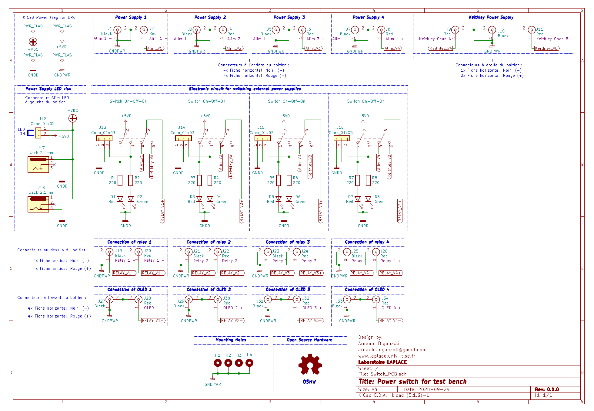
Integration into the housing
Enclosure - plastic, size: 220 mm x 110 mm x 44 mm (L x W x H)
PCB outline, size: 213,00 mm x 96,60 mm (L x W), from FreeCAD
Component placement and silk screen
| Placement | Silk screen |
|---|---|
| F.Mask + Edge.Cuts + F.CrtYd + F.Fab | F.SilkS + Edge.Cuts |
| Placement and Silk screen |
|---|
| F.SilkS + F.Mask + Edge.Cuts + F.CrtYd + F.Fab |
Top - Front Copper layer
Bottom - Back Copper layer
3D rendering
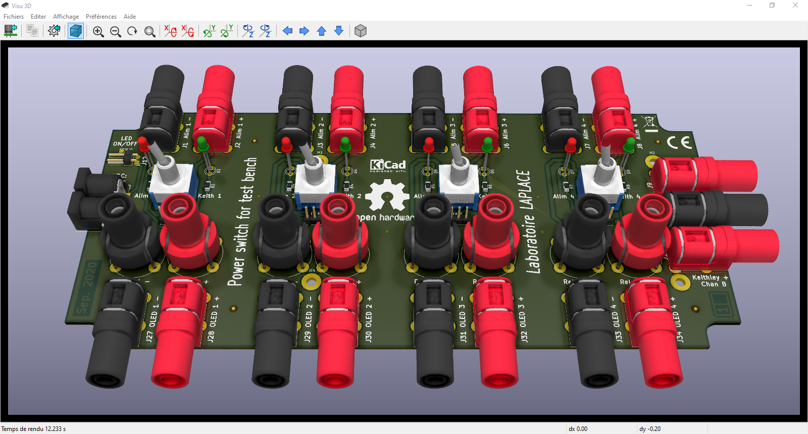
Integration of the electronic card in the case with the FreeCAD software
Sectional view
View of final STEP file for CNC
CHANGELOG
Ask about this board
No comments yet. Be the first to ask about this board.