ft-vac-control
PublicLoading 3D model… large boards can take a moment.
Use a Festool Bluetooth remote control with any vacuum
Use the Festool Bluetooth remote with vacuum extractors from other manufacturers.
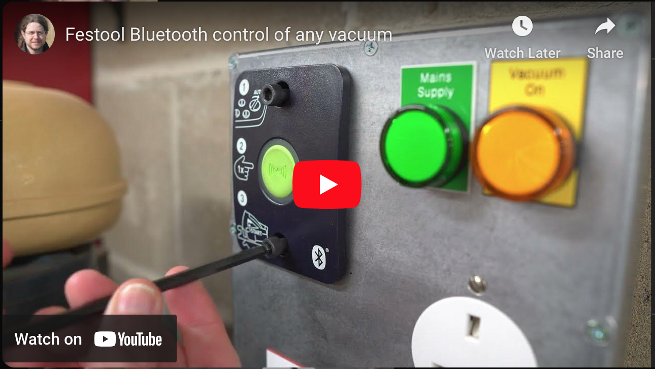
The project contains the schematics and PCB layout designed using KiCad 7, and the firmware (written in C) for the Raspberry Pi Pico to interface with a Festool No. 202097 Bluetooth Remote Control add-on.
Festool sell an upgrade for their CT26/36/48 vacuum extractors to give remote control using Bluetooth, CT-F I/M-Set. It has two parts: the "CT-F I/M" installs in the extractor and the "CT-F I" is the button that attaches to the end of the vacuum hose. The button then starts and stops the extractor. Paired cordless tools with their Bluetooth-enabled batteries can also control the extractor.
But I don't have a CT26/36/48 extractor from Festool, so I wanted to create an adaptor that uses the module and controls a standard power socket to control any device attached. With a custom PCB, a Raspberry Pi Pico, some firmware, a Solid State Relay, and an enclosure I had a working solution. Along the way I had to reverse-engineer the non-standard serial protocol and try to make sense of the bytes sent.
Features
- Allows connecting any vacuum extractor that has a physical switch capable of being always on. A vacuum with an NVR will not work.
- Works with an unmodified Festool No. 202097 receiver. It's Plug and Play. At a later date if I ever get a CT extractor I wanted to be able to use this module again.
- Has software safety features: automatically turns off if left on for an extended period. Uses the RP2040's hardware watchdog to shut off the power if the software stops for any reason.
- Should work with Festool cordless tools with their Bluetooth batteries (untested).
How it works
The Festool module has three electrical connections to the host vacuum: two for power and one for data. The data line is serial, probably bidirectional, and uses a form of Manchester encoding. For more details on the serial stream and commands, see the description of the traces captured with a logic analyzer.
The serial data from the receiver feeds the Raspberry Pi Pico via a BSS138 MOSFET as a level shifter. The Pico decodes the Manchester-encoded stream. When the Start/Stop commands are seen the software switches a Solid State Relay controlling mains AC supply to the output socket.
Wanting an excuse to learn KiCad, I designed a custom PCB to host the Pi Pico and a 4-pin 3.96 mm header to plug the CT-F I/M Bluetooth module into. The board contains a 240V switch-mode regulator providing 5V DC power to both the Pico and the CT-F I/M.
:zap: Mains voltage electricity can kill! :zap:
[!WARNING] This project description is not a guide and does not detail how to assemble a unit safely. If you are not sure how to build one that is safe and complies with local laws and regulations, DO NOT ATTEMPT TO RECREATE.
Bill of Materials
Parts on the PCB
| Part | Reference Designator | Description |
|---|---|---|
| MCU | U1 | Raspberry Pi Pico, the cheap one |
| 5V PCB mount PSU | PS1 | Vigortronix VTX-214-005-005 5W Miniature SMPS AC-DC Converter 5V Output |
| Fuse holder | F1 | 5.2x20mm PCB Fuse Holder W/Cover 6.3A 250VAC |
| PSU protection diode | D1 | Optional, diode to stop power from USB flowing back into the PSU. If not installed, bridge JP2 instead |
| RX data port | J1 | Connects to the Festool receiver module. 4 pin, 3.96mm pitch header with plastic tab cut off - e.g. JST B4P-VH(LF)(SN) |
| SSR driver header | J2 | 2 way, 2.54mm board-to-wire header for connecting to the input of the SSR |
| Wago 3 way PCB connector | J5, J6 | Wago part number 2604-1103 |
| Wago 4 way PCB connector | J7 | Wago part number 2604-1104 |
| Signal MOSFETs | Q1, Q2 | BSS138, in SOT-23 package |
| 10k Resistors | R1, R2, R3 | SMT 1206 package |
| 4.7uH | L1 | Inductor, RLB0913-4R7K |
| 100nF | C2, C4, C6, C7 | Decoupling capacitors, through-hole, 2.5mm pitch |
| 470uF 10V | C1 | Suntan TS13DJ1A471MSB040R 470uf 10V Low Imp Electrolytic Capacitor |
| X2 Capacitor | X2-Cap1 | Vishay BFC2-336-20224 220n 275V X2 Suppression Capacitor |
| Debug UART | J4 | Optional (usefully only for firmware development) |
| Test points | TP1, TP2 | Optional, do not populate |
| Aux port | J3 | Optional and currently unused |
| Reset switch | SW1 | Optional (usefully only for firmware development) |
Other mechanical and electrical parts
| Parts | Count | Description |
|---|---|---|
| Enclosure | 1 | 190mm x 190mm x 67mm die-cast aluminum box |
| Mains plug + inlet cable | 1 | I used a molded plug on a cable cut from an IEC lead |
| Power in strain relief | 1 | Cable Gland M16 10mm - e.g. 50616PA7001SET |
| Output socket | 1 | 13A Circular Panel Mount Socket Outlet, 13A - e.g. 735WHI |
| Green indicator | 1 | Panel mount, 22.5mm, 220-240v, to show if the incoming power is on - e.g. LEDTECGREEN230VAC |
| Yellow indicator | 1 | Panel mount, 22.5mm, 220-240v, LED lamp, to show if the vacuum power is on - e.g. LEDTECYELLOW230VAC |
| PCB standoffs | 5 | M4 - length dependent on the enclosure used |
| M6 x 35mm cap screws | 2 | Black, for securing the Festool receiver module |
| Custom M6 standoffs | 2 | To receive the M6 screws from the Festool receiver module. Length depends on the enclosure used, 39.1mm was correct for me |
| PCB screws | 5 | M4 x 8mm |
| SSR | 1 | Random on Solid State Relay, must be switchable by 5V DC - e.g. i-Autoc Panel Mount Solid State Relay, 25 A Max. Load, 280V AC |
| SSR cover | 1 | i-Autoc Kudom KPC-0A Solid State Relay Accessory Protective Cover Single Phase |
| SSR thermal pad | 1 | i-Autoc Kudom KTP-0A Solid State Relay Accessory Thermal Pad KSI/KSJ |
| Mains wiring loom | Assorted | Line, Neutral, Earth (CPC), sided appropriately for your max load. I used stranded 2.5mm2 |
| Bits 'n' Bobs | Assorted | Hardware to attach standoffs to enclosure and to mount the SSR, earth bonding nuts and bolds, and crimp eyelets and spade connectors |
License
The software, schematic designs and PCB layout contained in this repository are released under the MIT license.
Credits
I got the pinout for the Bluetooth receiver from YouTube channel "My Project Box". His video "Festool Bluetooth Hack / Mod works with any dust extractor!" shows a very neat solution with a different approach; avoiding any software.
On Github, user gilbertf published libft capable of both sending and receiving. It's not used by this project but his encoder appears to send the same bytes my decoder expects, which gave me some confidence that the implementation here is somewhat interoperable.
I used the Pi Pico KiCAD symbol and footprint from ncarandini/KiCad-RP-Pico
Other projects inspired by this one
This project helped Loriowar create a Festool receiver handler for Arduino.
No comments yet. Be the first to ask about this board.