tiny-matrix
Publictobleminer/tiny-matrix
Loading 3D model… large boards can take a moment.
Tiny LED matrix
This board is a tiny 8x8 monochrome LED matrix powered by a STM32F030. The board is just 11x11mm in size and fully JLCPCB assembly ready. The board has been panelized in a 2x3 grid to use the available space on JLC's PCBs more efficinetly. The device uses a novel, BGA style assembly procedure to achieve the smallest footprint possible.
Ordering
When ordering through JLC there is a small tradeoff to be made. You can either order the boards with 1mm thickness and will need to perform a small mechanical modification on your TC2030 but get the smalles formfactor possible or order the boards in 1.6mm thickness making your board stack thicker but sparing you from hacking up your TC2030. If you are not into placing components like A LOT I'd recommend using JLCs assembly service.
Programming
The boards are fully functional while in the panel. I'd recommend leaving at least one pair of boards inside the panel since the TC2030 cable can not be fixed to board easily anymore once the board sandwich has been assembled. Note that you might have to file down the allignment pins of the TC2030 if you want to use it with assembled boards, since they are too long for the pogo pins to reach the pads with a 1mm PCB.
Assembly
While the matrix boards are fully functional while inside the frame they are intended to be soldered back to back. To solder the boards together first remove them from the panel. After that wet the backsides of the boards with a liberal amount of good quality flux. Then drag a soldering iron wetted with lots of solder over the testpoints on the backside of the board. This should create fairly uniform solder balls ontop of the pads. Once all boards are preapred with solder balls apply more flux and stick one controller board and one LED board together. Make sure they are alligned properly. Now you can reflow the two boards together. You can do this either manually with hot air or in a reflow oven. Situate the stacked boards LEDs down, since they are the most temperature sensitive parts. If you have any level of familarity with soldering BGA components you will notice when reflow is complete right away. Don't be afraid to heat the boards for a little longer, the STM32F030 seem to be able to take quite a lot of abuse.
Firmware
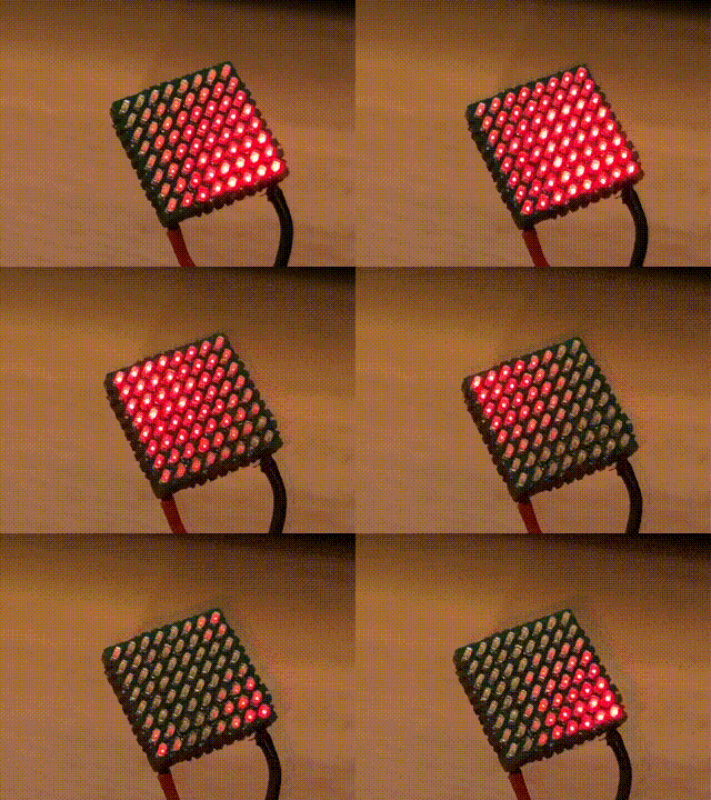
The directory firmware contains a simple example displaying the pattern from the gif
above.
No comments yet. Be the first to ask about this board.