zx-spectrum-pico-rom
PublicLoading 3D model… large boards can take a moment.
zx-spectrum-pico-rom
A Pico-based switchable ROM interface for the 48K ZX Spectrum
This is a ROM interface board for the 48K ZX Spectrum. It presents a new, selectable ROM image for the machine, replacing the 1982 BASIC one found in the IC on the Spectrum's PCB.
There are lots of these around, all based on ROM and EEPROM chips. My design is based on a Raspberry Pi Pico microcontroller programmed to emulate a ROM chip.
The main advantage of doing it this way is that the Pico has enough memory for several ROM images, and enough flash for as many ROMs as anyone would likely ever want. A button allows the loaded ROMs to be cycled.
It works like this (click through for YouTube video):
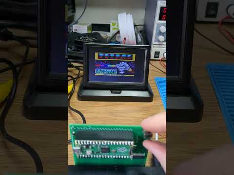
https://youtube.com/shorts/0Ot5mol2f5A?feature=share
Update Dec'24: I used this Pico ROM project as the basis for a bit of experimentation with the Z80's non maskable interrupt (NMI) on the Spectrum. Updated software and description are here. If you're after a simpler version of the Pico code to do a simple ROM emulation task, that's probably the version you want.
Update Feb'25: I further used this Pico ROM project as the basis for adding a carefully timed non maskable interrupt (NMI) which fires each frame at the point the Spectrum is about to draw the lower border. Not sure how much value there is there, but if anyone's interested the subproject is here.
Design
The Z80's address and data bus lines are connected to the Pico's GPIOs. GPIOs are limited on the Pico (there's only 26), so only 14 of the 16 address lines are connected. A bit of external logic handles the top two. The software on the Pico sits spinning, watching for that logic to indicate that A14, A15 and /MREQ are all zero, that being the indication of a ZX Spectrum ROM memory access by the Z80. When that condition is met the address the Z80 is requesting (in the range 0x0000 to 0x3FFF) is found from the GPIOs connected to the address bus, and the value from that offset in the currently enabled ROM image is fetched. The 8 bits of that value are placed on the 8 GPIOs connected as outputs to the Z80's data bus.
Hardware design
The Spectrum is +5V, the Pico is 3V3, so every bus or signal pin needs level shifting, down on the way into the Pico, up on the way out.
GPIO count is also pretty tight, which is why the external logic is required. It's a simple 3-input OR gate which ORs A14, A15 and /MREQ. The output of that gate is fed into the Pico, saving 2 GPIOs.
It's important that the device doesn't assert an output value onto the Z80's data bus until it needs to. This is controlled by hardware. The data bus level shifter is set permanently to the Pico->ZX direction, but is left off (via its chip-enable line) until the ROM is being read. The /CE line is pulled low by the output of the 3-way OR gate, so when the Z80 is reading from ROM the level shifter is turned on and the value on the data bus is connected to the Z80. As soon as the /MREQ line goes high again the OR result goes true and the level shifter is turned off again.
The Pico needs the ability to reset the Z80, which gets very unhappy if the ROM program it's running is suddenly changed from underneath it. The Z80's /RESET line is connected to a GPIO via a transistor; the line is pulled low via Pico software when the Pico changes the ROM image in order to reset the Z80.
There's a single user input button connected to the one remaining GPIO on the Pico. In the current software this cycles the ROM to the next one in the (compiled in) sequence. The Pico's ADC is available so more buttons and a better user interface could be constructed using a resistor ladder.
The Z80's /M1 line is connected to a Pico GPIO input. This isn't required for the typical use case, but it makes the device a useful test bed for running the ZX Interface One ROM - see below.
Caveat
Feb'25: I was playing around with one of these interfaces, and found myself wanting to re-enable the Spectrum's ROM with the interface still plugged in. (I needed the Pico for something, but with the Spectrum's own ROM.) So I cut the /ROMCS track on the back of the interface, and then spent some time trying to figure out why the Spectrum wasn't working.
Eventually it dawned on me: when I cut the track the Spectrum's ROM IC was re-enabled, and it started to drive the data bus. But the U4 level shifter was still working on the interface, which meant that was also driving the data bus. That's a bad thing, the two ICs were both trying to be outputs and were driving each other's data lines. The Z80 was getting garbage on the data bus, and I think I was rather lucky nothing got damaged. I removed the level shifter to complete my experimentation.
So, um, don't do that. :)
Construction
The gerbers archive for upload, for example, JLCPCB, is srom/fab1.2/fab1.2.zip. It's a simple 2 layer board.
Note: As of this writing I've not actually had one of these made. I hand-modified my v1.1 board with the errata from v1.1. The v1.2 design has had those modifications added so I'd expect it to work exactly the same as my modified v1.1 board. But I haven't tried it yet. The switch, in particular, might yet require another tweak depending on what piece of hardware is chosen. I used a 6mm x 6mm right angle switch.
There's nothing complicated about the soldering. Do the big ICs first and the Pico sockets, if you use them, last.
Software Design
The software which runs on the Pico is built on a simple loop which does this:
- spin, waiting for the ROM-being-accessed signal to come in
- read the 14 bits of the address bus from the GPIOs
- convert that bit pattern into an offset
- find the value of the byte at that offset into the currently used ROM image
- apply the 8 bits of that byte value to the 8 output GPIOs connected to the Z80's data bus
- go back to the top
The glaring issue here is speed. Pg8 of the Z80 manual says that the timing for M1, the instruction fetch, is most time critical. The data is sampled off the bus one and a half clocks after /MREQ goes low. On the Spectrum's 3.5MHz Z80 that's 4.28571428571e-07 seconds, so about 430ns. Despite several efforts at optimisation I've been unable to get the Pico to reliably return the data value inside that time frame. Much to my frustration, v1.2 of the software still requires an overclock from 133MHz to 140MHz.
The Z80 starts up faster than the Pico which requires half a second or so to get going. This means the Z80 is asking for ROM instructions before the Pico is ready to provide them. The Pico resets the Z80 as soon as it, the Pico, is ready to go. That's why there's a colourful display of randomness for a moment at startup.
ROM Images
The device is permanently enabled; the original ROM chip in the Spectrum is disabled while the interface is attached.
The Pico software contains the ROM images it's compiled with, the first of which would typically be the original ZX ROM from 1982. I've added a diagnostics ROM and the Gosh Wonderful ROM since they are free to redistribute. Games ROMs are not included in the source release but they can be added fairly easily. A Linux command like:
xxd -i spaceraiders.rom
will convert a ROM image into 'C' array data which can be dropped into roms.h.
Switcher ROM
Some of the ROMs look superficially similar, like the original 1982 ROM and the Gosh Wonderful ROM. It got confusing trying to work out what was running. I wanted a row of LEDs across the top of the device to act as an indicator of which ROM was in use, but I didn't have any GPIOs to implement it with. So I added an extra ROM image I called the "switcher" ROM.
This program is written in 'C' and compiled with Z88DK. The source is in the firmware/switcher directory. It presents a banner saying what ROM is coming up next, then sits indefinitely buzzing the Spectrum's border.
When the user input button is pressed, the Pico software selects this switcher ROM and resets the Z80 to start it running. The banner appears on the Spectrum screen. About a second later an alarm goes off in the Pico, the handler for which selects the next ROM in sequence and resets the Z80 again. Thus the switcher ROM appears as a banner on the Spectrum screen between each ROM switch.
ZX Interface One
This device can also switch in and out the ZX Interface One's ROM. This is an 8K ROM which, in the actual IF1, is paged in by hardware on 3 magic address accesses: it's paged in when the Z80 requests an instruction from addresses 0x0008 and 0x1708, and paged out again when the Z80 requests an instruction from address 0x0700. It's early days with this idea, but that boils down to this code:
if( (rom_address == 0x0008) || (rom_address == 0x1708) )
{
  rom_image_ptr = __ROMs_if1_rom;
}
else if( rom_address == 0x0700 )
{
  rom_image_ptr = __ROMs_48_original_rom;
}
This needs the /M1 input merged into the logic, but that's the idea. The joys of programmable devices like the Pico, as opposed to hardware. :)
There's a macro in the firmware source to switch in an early IF1 paging version of the code. It seems unreliable, but I won't be persuing this any further with this project.
Note: the v1.1 board doesn't have the /M1 signal connected. The v1.2 board has it connected into GPIO15. The software doesn't have the /M1 signal taken into account as yet.
Bill of Materials
You will need:
3x 74LVC245 Bus transceiver
Bus transceiver, used as a level shifter
1x 3216 SMD Diode
Schottky Diode for Pico input protection
1x 4075 OR gate
3-way 3-input OR gate
4x 3216 SMD 0.1uF capacitor
Decoupling capacitor
1x PMBT2222A SMD Transistor
NPN Transistor for /RESET
1x 3216 SMD 1K Resistor
1K Resistor for /RESET
Also:
1x Raspberry Pi Pico with pins and sockets if you want them
1x ZX Spectrum Edge Connector socket
1x SPST switch any single pole, single throw switch to use as an input button. The footprint
on the board matches one I happen to have had, assume you'll add it on flying leads.
Licence
Distributed as free software and hardware design under the GPL. The ROM images have their own licences, see the ROMs/ directory.
Derek Fountain February 2023
No comments yet. Be the first to ask about this board.