RTB_C02
PublicLoading…
RTB_C02


My C02 module is designed to trace DCC Railcom traffic for decoder debugging and development purposes. In particular the Railcom capture is an important feature and helps to validate if a decoders is RCN-217 compliant. The C02 uses the Vt100 terminal emulation control codes for its user interface. Therefore a VT100 capeable terminal program is a must (e.g. putty, teraterm). The USB interface is galvanically isolated from the DCC track potential.
User Guides
- User Guide - DE
- User Guide - EN
<img src=supplemental/images/C02_main.jpg width=860>
Hardware
My current PCB layout uses SMD footprints with 0.5mm pitch and mostly 0603 but some 0402 parts. Reflow soldering is my recommendation, but with some experience handsoldering may also be possible.
PCB
- 4-layer PCB, FR4, 1.6mm
- CPU: mega328pb
- USB: FT232x (Mini-B)
- DC/DC: NME0505SC (or compatible)
Kicad
Dependency
:yellow_circle: Requires my Kicad project library RTB_SamacSys in the same directory tree.
Firmware
Filename structure: { pcb }{ code }{ version }.hex
Example: C02F0001.hex
| Description | |
|---|---|
| pcb | Name of matching hardware (C02) |
| code | Type of code contained (R=rom, B=bootloader, F=flash, U=bld update, P=UPDI/SPI factory code) |
| version | Release version (####) |
ISP
The fuse settings as well as the P-code (C02Pxxxx.hex) has to be installed by using the ISP.
Details
CAUTION: Before connecting the ISP, the jumper next to the ISP 6-pin interface must be closed (yellow jumper on picture).
| Fuses Setting | Bootloader Install |
|---|---|
| <img src=supplemental/images/C02_updi_fuses.jpg width=500> | <img src=supplemental/images/C02_updi_memory.jpg width=500> |
Bootloader
Subsequent main code updates can be done via uploading the new firmware (C02Fxxxx.hex) file to the bootloader console prompt.
Details
-
press F1 to switch to console screen
-
press ^b (ctrl-b) to enter bootloader
-
upload the firmware file (C02Fxxxx.hex)
-
press x to exit the bootloader
<img src=supplemental/images/C02_debugIF.jpg>
Software
Operating the C02 is within the terminal window.
Terminal screens
Below some example screens of the different functional sections. The screens (called aspects) can be switched by pressing F1-F7. All screens are updated in real-time speed, ensuring always up-to-date information shown.
| Aspect | Example |
|---|---|
| F1: Console prompt. | <img src=supplemental/images/C02_screen_F1.jpg width=500> |
| F2: DCC/Railcom line by line real-time trace. | <img src=supplemental/images/C02_screen_F2.jpg width=500> |
| F3: DCC/Railcom decoder payload | <img src=supplemental/images/C02_screen_F3.jpg width=500> |
| F4: DCC/Railcom timing | <img src=supplemental/images/C02_screen_F4.jpg width=500> |
| F5: DCC command set | <img src=supplemental/images/C02_screen_F5.jpg width=500> |
| F6: Railcom response set | <img src=supplemental/images/C02_screen_F6.jpg width=500> |
Images
This is how the PCB looks like.
<img src=supplemental/images/C02_samples.jpg width=260> <img src=supplemental/images/C02_closeup.jpg width=260> <img src=supplemental/images/C02_usecase.jpg width=260>
YouTube
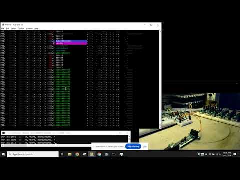
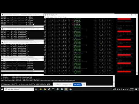
Some short videos to see the DCC/Railcom logger in action.
No comments yet. Be the first to ask about this board.