rtb_c12
PublicLoading 3D model… large boards can take a moment.
RTB_C12



My homebrew RTB C12 Micro Booster implements a booster, DCC generator and Real-time Railcom detector. The booster is optimized for N-scale in respect to track voltage and current.
User Guides
- User Guide - DE
- User Guide - EN
Booster features
- FDX
- FDX bus (2Mbps full duplex)
- DCC protocol generator
- unlimited decoder stack depth
- DCC bandwidth monitor
- DCC-A protocol (incl. stretched start bit)
- DCC-R protocol (incl. update of RTB decoder on main)
- MDU protocol generator
- Zimo MDU (Multi Decoder Update)
- update of MS and MN decoder
- can update multiple MN/MS decoder concurrently
- DECUP protocol generator
- Zimo DECUP (Decoder Update)
- update of MX decoder
- Doehler & Haass update-protocol generator
- update of D&H decoder
- Booster
- Software programmable output voltage (3..18V)
- 1A continuous current (1.5A peak)
- Current limiter
- Short circuit detection
- Configurable bridge dead time (170ns..3500ns)
- DCC signal timing adjustable [micro sec granularity]
- Railcom Cutout timing adjustable
- Up to 500kHz fast signaling
- Voltage and current measurement
- Railcom Detector
- channel 1 / channel 2
- detects unlimited number of decoder
- Railcom polarity detection
- Railcom timing capture for decoder analysis
- Service Mode
- read/write DCC decoder in “service mode”
- ACK current detector adjustable
- Firmware update over the bus
Hardware
The PCB layout uses SMD footprints with 0.4mm pitch and mostly 0603 parts. Reflow soldering is recommended, but with some experience handsoldering is also possible. Further, the PCB has been optimized for automated assembly (BOM and Position files as CSV).
PCB
- 4-layer PCB, FR4, 1.6mm
- CPU: AVR64DB48
- H-Bridge: BD63573NUV
- Voltage: OPA521
Kicad
Firmware
Filename structure: { pcb }{ code }{ version }.hex
Example: C12F0001.hex
| Description | |
|---|---|
| pcb | Name of matching hardware (C12) |
| code | Type of code contained (R=rom, B=bootloader, F=flash, U=bld update, P=UPDI factory code) |
| version | Release version (####) |
UPDI / Fuses
The fuse settings as well as the P-code (C12Pxxxx.hex) has to be installed by using UPDI.
| Fuses Setting |
|---|
| <img src=supplemental/images/C12_fuses.jpg width=500> |
Images
YouTube
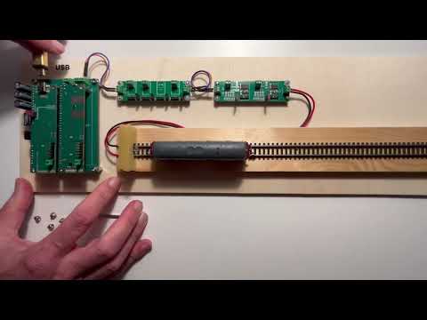
See the C12 booster in action.
This project is intended for hobby use only and is distributed in accordance with the Apache License 2.0 agreement.
No comments yet. Be the first to ask about this board.