rtb_d22
PublicLoading 3D model… large boards can take a moment.
RTB_D22



My Homebrew D22 decoder is a double sided mobile decoder with Plux16 connector. The decoder is designed to integrate into the RTB digital control infrastructure.
See also
- RTB_D12 - custom (Fleischmann V100)
- RTB_D13 - custom (Minitrix coach)
- RTB_D15 - custom (Minitrix V160)
- RTB_D16 - NEM651
- RTB_D20 - NEM651
- RTB_D21 - Next18
- RTB_D23 - NEM652
User Guides
- User Guide - DE
- User Guide - EN
Decoder features,
- Plux16 connector
- DCC
- DCC-A automatic logon
- DCC-R protocol extension
- Service Mode Programming
- Railcom
- Channel 1/2
- POM, xPOM
- DYN: Speed, QoS, Track-voltage, Motor-current, AUX-current, Temp, Distance travelled
- Double sided
- Dimension: 15 x 11 mm
- 7-20V track voltage
- heartbeat LED
- adjustable max motor current (default 300mA)
- adjustable max AUX current (default 500mA)
- over temp protection
- Function output: LF/LR (dimmable, 1.4kHz) open drain
- Function output: AUX1/AUX2 (dimmable, 1.4kHz) open drain
- Function output: AUX3/AUX4 logic level (3.3V) using LS A/B ports
- Function output: AUX5/AUX6 logic level (3.3V) or ZBCLK/ZBDAT (3.3V)
- optional external buffer capacitor
- <10mA idle power consumption
- Firmware update over main tracks via DCC-R protocol
Hardware
The current PCB layout uses SMD footprints with 0.5mm pitch and 0402 parts. Reflow soldering is mandatory whereas handsoldering near to impossible.
PCB
- 6-layer PCB, FR4, 15 x 11 x 0.8mm (double sided)
- CPU: AVR64DD28
- Motor bridge: DRV8231
Kicad
Dependency
:yellow_circle: Requires my Kicad project library RTB_SamacSys in the same directory tree.
Firmware
Filename structure: { pcb }{ code }{ version }.hex
Example: D22F0001.hex
| Description | |
|---|---|
| pcb | Name of matching hardware (D22) |
| code | Type of code contained (R=rom, B=bootloader, F=flash, U=bld update, P=UPDI factory code) |
| version | Release version (####) |
UPDI
The fuse settings as well as the P-code (D22Pxxxx.hex) has to be installed by using UPDI.
Connecting the decoder via its track pins to a 5V(DC) power supply will boot its CPU. This way, its easy to program the fuses and flash.
<img src=supplemental/images/D22_updi.jpg width=800>
Details
| Fuse Setting | P-code Install |
|---|---|
| <img src=supplemental/images/D22_updi_fuses.jpg width=500> | <img src=supplemental/images/D22_updi_memory.jpg width=500> |
Images
| top | bottom |
|---|---|
YouTube
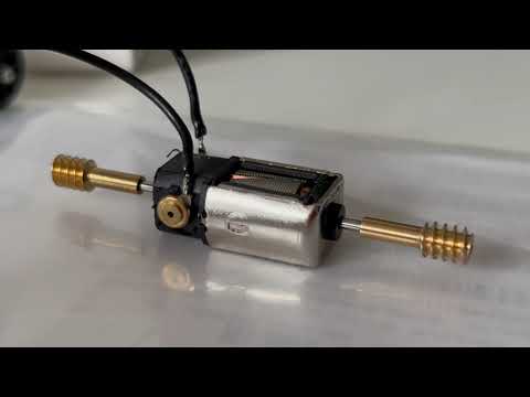
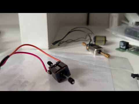
Some YouTubes to see the D22 decoder in action.
This project is intended for hobby use only and is distributed in accordance with the Apache License 2.0 agreement.
No comments yet. Be the first to ask about this board.