digi-spherometer
PublicLoading 3D model… large boards can take a moment.
A Digital Spherometer
Converting the sagittal measurement (SAG) from a dial indicator and converting in your head to a sphere radius is a pain.
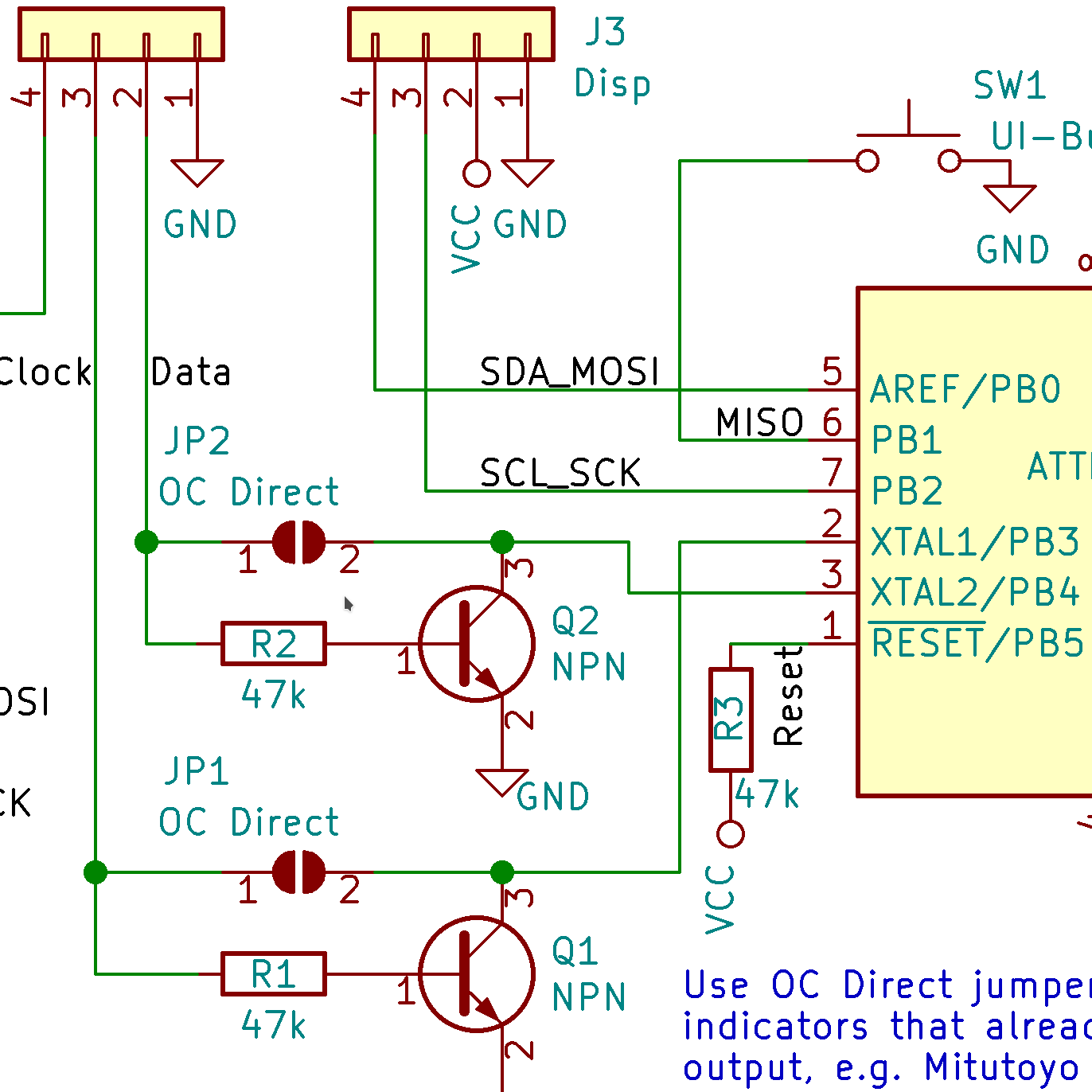
This project uses a microcontroller to make this more pleasent: it reads out the digital indicator and converts the reading to a sphere radius value printed on an OLED display. It also adds some other nifty features, such as converting this into the ƒ/N for your mirror size. See firmware-page for feature details.
The microcontroller is an ATTiny85, the display is a 0.96" SSD1306, or 1.3" SH1106 compatible 128x64 OLED display with I²C interface.
Supported dial indicators are Mitutoyo 543 (good, industry-standard quality) and a generic autoutlet-indicator (relatively cheap, has 1μm resolution but no documented accuracy figures. Sells under many different names).
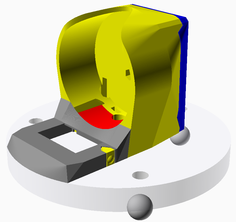
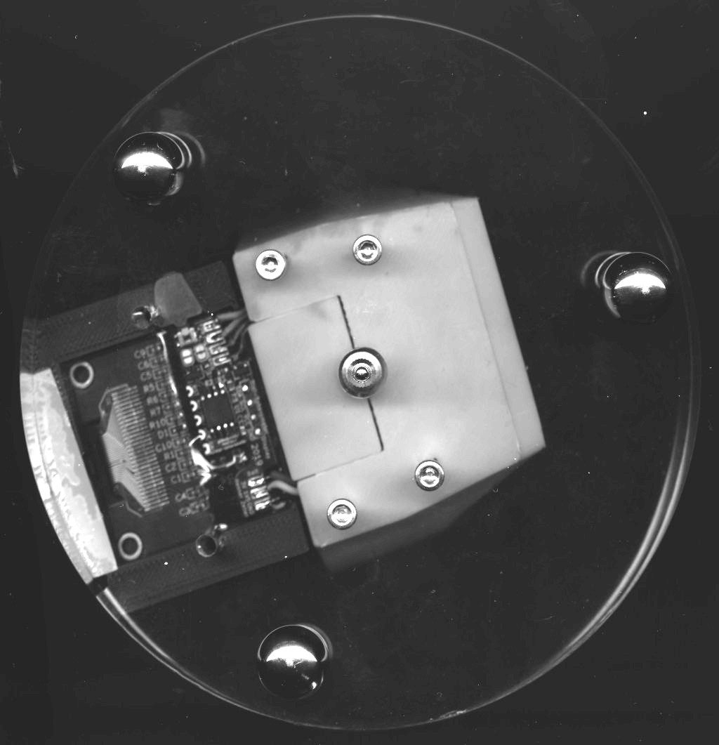
The case to hold the dial indicator, microcontroller+display and batteries is 3D-printed, the base can be laser-cut or machined from some metal plate.
Quicklinks
| Case | Electronics | Firmware | Calibration |
|---|---|---|---|
 |  |  |  |
User Manual
Like any Spherometer, we first need to zero the device on a reference surface. Typically this is done on a flat surface plate, so this spherometer allows for that: place it on a flat surface and set the dial indicator to zero.
Unlike other spherometers, this device also allows for another (experimental) mode: using the grinding tool as a reference surface. The convex shaped tool has the same (but inverted) curvature as the mirror, so this can be used as a reference, if the tool and mirror are already sufficiently mated. The spherometer then can do the math to derive the value from that.
To use that mode, place the spherometer on the tool (make sure the balls and indicator rest on the tiles not hitting a seam), and zero the dial indicator. The arrow-shaped button the right side of the display allows to toggle between the reference mode. The selected mode is highlighted.
| Reference on Surface Plate | Reference on Tool |
|---|---|
The tool reference is probably a bit less accurate, but it does not require you to be in posession of a flat surface plate.
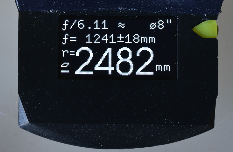
After the device is zeroed, place it on the mirror. It now shows all relevant values on one screen. This is what you see from top to bottom:
- The ƒ/N value for a given mirror size. The mirror size (chosen here:
⌀8") can be cycled through from a list with the arrow-button. - The focal length including error margins derived from dial-indicator error and spherometer leg-radius error.
- The radius is shown in a large font
On the bottom left you see a symbol indicating which reference surface this was against. There are two symbols indicating flat surface and tool referenced (same symbols as used in the zero screen).
| Millimeter | Inch |
|---|---|
So in this example we see in one screen, that this is a mirror with a radius of about 2482mm, a focal length of 1241mm which is ƒ/6.11 for this 8" mirror. The reference surface was a flat surface plate.
Switching between metric and inch on the dial indicator automatically switches the calculated values to the corresponding units.
The device does not need an additional power button: it auto-detects when the drop-indicator is switched off and goes to sleep.
No comments yet. Be the first to ask about this board.