arduino_pro_mini_xl
PublicLoading 3D model… large boards can take a moment.
Arduino Pro Mini XL
Overview
The Arduino Pro Mini XL is a compact microcontroller board based on the ATmega1284P, designed to extend the capabilities of the standard Arduino Pro Mini while retaining its familiar form factor. With increased memory, additional I/O pins, and enhanced features, this board is well-suited for embedded applications requiring greater processing power and connectivity than the ATmega328P-based Arduino Pro Mini can provide. It integrates seamlessly with the Arduino ecosystem, making it accessible to hobbyists, engineers, and developers alike.
Features
- Microcontroller: ATmega1284P
- Flash Memory: 128KB
- SRAM: 16KB
- EEPROM: 4KB
- Digital I/O Pins: 22
- Analog Input Pins: 2
- Analog Comparator: 1
- PWM Channels: 8
- UARTs: 2
- SPI: 1
- I2C: 1
- Operating Voltage: 5V
- Clock Speed: 20/16/8MHz
- Form Factor: Compatible with Arduino Pro Mini
Schematic diagram
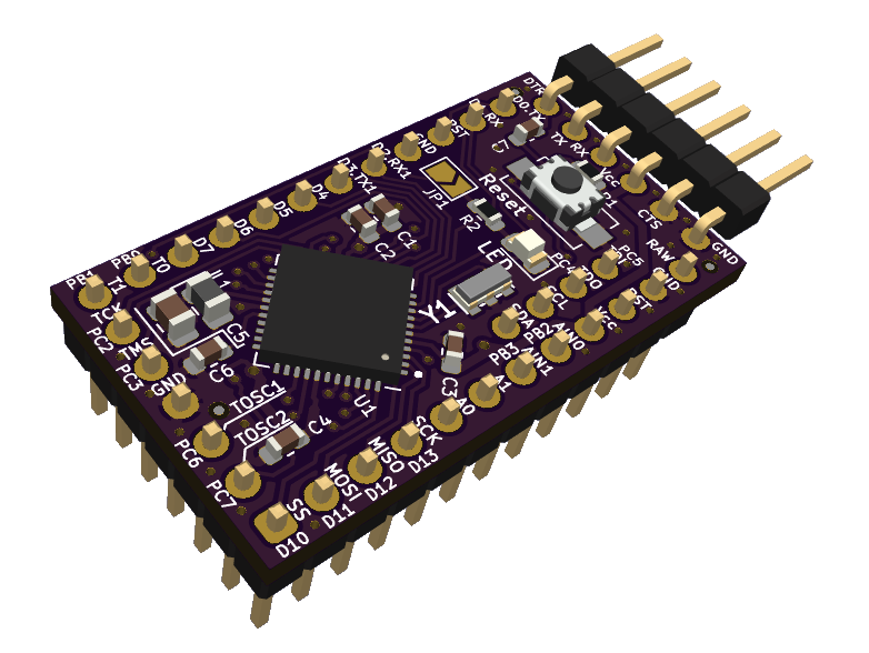
Module visualisation
(click on the image to see the 3D model)
Assembly
Production files
Production files can be found here.
Software Compatibility
The Arduino Pro Mini XL is supported by the Arduino IDE through the MightyCore board package, which provides board definitions for the ATmega1284P.
Installing MightyCore
To configure the Arduino IDE:
- Open the Arduino IDE.
- Navigate to
File>Preferences. - Add the following URL to the
Additional Boards Manager URLsfield:https://mcudude.github.io/MightyCore/package_MCUdude_MightyCore_index.json - Click
OK. - Go to
Tools>Board>Boards Manager. - Search for "MightyCore" and install the package.
After installation, select "ATmega1284P" under Tools > Board, and configure the variant and clock settings as needed.
Getting Started
- Connect the Board: Attach an FTDI-compatible cable or adapter to the 6-pin programming header.
- Configure the IDE: Select the ATmega1284P board and the appropriate serial port in the Arduino IDE.
- Upload a Sketch: Use a simple sketch, such as "Blink," to test functionality.
void setup() { pinMode(PIN_PC6, OUTPUT); // Onboard LED // Don't forget to close JP1. } void loop() { digitalWrite(PIN_PC6, HIGH); delay(1000); digitalWrite(PIN_PC6, LOW); delay(1000); } - Verify Operation: Confirm that the onboard LED blinks, indicating successful setup. Don't forget to close JP1.
Burning the Bootloader
To burn the bootloader using an ISP programmer:
- Connect the ISP programmer to the board’s pins.
- In the Arduino IDE, select the ATmega1284P board and your programmer.
- Choose
Tools>Burn Bootloader.
Consult the MightyCore documentation for correct fuse settings.
Troubleshooting
- Upload Failures: Verify board and port settings; check FTDI connections and drivers.
- Power Issues: Ensure input voltage is 5V (VCC); inspect for shorts. Board has no RAW input
- Pin Mapping: Confirm pin assignments, as they differ from the ATmega328P.
Physical Specifications
- Dimensions: Comparable to the Arduino Pro Mini (18.5mm x 33mm).
Reporting bugs
Acknowledgments
Thanks to the Arduino community and the MightyCore developers for enabling support for the ATmega1284P.
License
Copyright © 2020-2025 Michal Protasowicki
This project is released under CERN Open Hardware Licence Version 2 - Permissive.

Support
If You find my projects interesting and You wanted to support my work, You can give me a cup of coffee or a keg of beer :)
No comments yet. Be the first to ask about this board.