donutdongle
PublicLoading…
Donut Dongle
Arduino Nano based hub that connects your digital and analog console switching setup with the RetroTink 4K and/or RetroTink 5x / OSSC for Auto Profile switching
The Donut Dongle connects to a switch in a way that allows it to see which port is active. When a console powers on (auto-switching) or an input is manually selected, the Donut Dongle sends a serial command to the RetroTink 4k (or IR signal to the RT5x, OSSC) telling it to load a profile. For the RT4K, the profiles can either be defined as remote profiles; those configured in the menu for the remote buttons. Or they can be SVS profiles which are configured on the RT4K's SDcard.
For details, refer to the "How to Use" section below.
[!TIP] If DIY is not your thing. I have assembled versions for gScart/gComp and MT-VIKI/TESmart/Extron/db9 available in my Ko-fi shop.
[!NOTE] NEW version allows:
- Alternate SVS Profile System - allows a different set of profiles to load. Explained in the "New IR Remote Control functionality" section below.
- Fallback - feature that allows a switch that reports having no active inputs to change profiles over to one that does.
- MT-VIKI Disconnection Detection - when an input is powered off and on, the profile is resent.
- Disable MT-VIKI beeping by pressing the "#" button on its remote.
- front case buttons/remote NOW change profiles on the MT-VIKI HDMI switch. Thanks to Arthrimus!
- auto-switching on Extron Matrix switchers that support DSVP. Works with RGBS/HV and HDMI/DVI signal types.
- Support for older Extron Crosspoint (non plus) matrix switchers
Use the follow Options to enable:#define automatrixSW1 true // set true for auto matrix switching on "SW1" port #define automatrixSW2 false // set true for auto matrix switching on "SW2" port uint8_t const ExtronVideoOutputPortSW1 = 1; // For non "Plus" Extron Matrix models, must specify video output port that connects to RT4K uint8_t const ExtronVideoOutputPortSW2 = 1; uint8_t const vinMatrix[65] = {0, // MATRIX switchers // When auto matrix mode is enabled: (automatrixSW1 / SW2 defined above) // set to 0 for the auto switched input to tie to all outputs // set to 1 for the auto switched input to trigger a Preset // set to 2 for the auto switched input to tie to "ExtronVideoOutputPortSW1" / "ExtronVideoOutputPortSW2" // // For option 1, set the following inputs to the desired Preset # // (by default each input # is set to the same corresponding Preset #)
More Images...
Thanks to
- Justin Peacock for the amazing case design
- HerraAAV3 from the RetroTink discord for the VGA Adapter case design
- Mike Chi for help with the open drain serial bits
- @niquallis, @UstSte, and last but not least Aru for beta testing
Supported Switches
(current list, but not limited to)
| Switch | Supported | Notes |
|---|---|---|
| MT-VIKI 8 port HDMI | yes, confirmed first hand. RT4K remote can also change inputs and profiles. | Front case buttons and included IR remote also change profiles! Disable MT-VIKI beeping by pressing the "#" button on its remote. |
| TESmart 16x1 HDMI | yes, confirmed first hand | RT4K remote can also change inputs and profiles. |
| TESmart 8x1 HDMI | unconfirmed, but should work, let me know! | |
| gSCARTsw / gCOMPsw | version 5.x confirmed by @niquallis and @UstSte, thanks so much for your help! | Manual input selection works too! |
| Extron RGBHV sw6 | yes, confirmed first hand | |
| Extron DXP 88 | yes, confirmed first hand | at the moment, works with Presets only. Preset 1 is Profile/SVS 1. On Extron sw2 port Preset 1 is SVS 101, etc |
| Extron CrossPoint, MVX, etc | same as DXP 88 above. at the moment, Presets only | |
| Extron CrossPoint E-series | yes, works with Presets and Input changes | Must set ExtronVideoOutputPortSW1 / SW2 variable to output connected to RT4K |
| Extron SW4 VGA Ars | yes, confirmed by "Nobody" on the RT4K Discord | |
| Otaku Games Scart 10 | Jumper moved to "L" and with required mod , SVS=0; must also be set in the Otaku .ino for the DD to respond | modded switch works on its own, but connecting through the DD is mostly useful if your Otaku mod doesn't include the buffer IC |
Connections
- Connect 4 switches Total
- 2x gscart/gcomp
- 2x Extron, 2x TESmart, or 1 of each
- 1x usb-c port for power/programming (on Arduino Nano)
- 1x 3.5mm "TX OUT to Retrotink 4K VGA adapter" port
- 1x IR Emitter (required for OSSC, RT5x (RT5x must be on firmware version 3.7 or higher))
- 1x IR Receiver (optional for better reception and IR remote customizations)
Layout Example
- TESmart 16x1 HDMI switch & 2x gSCART/gCOMP
- VGA Passthrough adapter
- TESmart adapter
- gScart EXT pushpin adapter
- Case closed
- ribbon cables fold over and come out slots in the back of case
Connection Acccessories
gscart/gcomp EXT connector (plug-n-play)
The spring pins allow it to stay "sandwiched" in place by the lid
TESmart connector
MT-VIKI / Extron / DB9 adapter
Parts listed in BOM below
Alternate Extron connection type:
- DB9 male to 3.5mm (connects to alt sw1 / alt sw2 port instead of 2x5 header)
- Higher quality and much longer cord than the standard 2x5 cable
New IR Remote Control functionality
When using the optional IR Receiver, the IR reception of the RT4K can be been greatly enhanced. You can think of it as an IR repeater, but instead talks to the RT4K via Serial for solid communication. Since the Donut Dongle is in the middle, other remote features can be added such as:
-
Alternate SVS Profiles: Have you ever wanted to add CRT effects to all of your existing SVS profiles? Or wanted all your profiles to output at 1080p instead of 4K? With this feature you can create a set of SVS profiles that have these changes and activate the system with the remote. Pressing the "SAFE" button twice + 1 - 9 buttons will allow you to configure 9 different sets of these profiles per regular profile to load instead of the regular one you created. For example: Instead of SVS profile S1_SNES.rt4 loading, S1001_SNES.rt4 will load instead after activating with the "SAFE"x2 + 1 button. Here are some more examples so you can see the pattern used for creating these:
"SAFE"x2 + x button = Sx001_SNES-CRT.rt4, where x is the number button selected and 001 is the S1_ profile represented in 3 digits.
"SAFE"x2 + 2 button = S2001_SNES-1080p.rt4
"SAFE"x2 + 3 button = S3001_SNES-Zoomed.rt4
"SAFE"x2 + 4 button = S4001_SNES.rt4
"SAFE"x2 + 5 button = S5001_SNES.rt4
"SAFE"x2 + 6 button = S6001_SNES.rt4
"SAFE"x2 + 7 button = S7001_SNES.rt4
"SAFE"x2 + 8 button = S8001_SNES.rt4
"SAFE"x2 + 9 button = S9001_SNES.rt4-
The name following the "_" can be changed as well. So a name like S1001_SNES-CRT.rt4 can be used to better describe. Only the naming pattern before the "_" is important.
-
When SVS profile S2 normally would load, Sx002 would load instead where x = the number button chosen prior and 002 represents the S2 profile. S2100_NES.rt4 for example would be the 2nd Alternate profile for S100_NES.rt4. It's up to you to create these alternate sets of profiles on your SD card of course. To disable this feature and return to your normally configured profiles, press "SAFE"x2 + 10, 11, or 12 buttons on the remote.
-
-
SAFE button once + profile button 1 - 12 loads SVS profiles of your choosing. By default is SVS 1 - 12. Configured with auxprof[] in the Settings section of the .ino
-
Normally, if you power on your console before waking the RT4K, the RT4K will have not seen the profile change. Using the remote's POWER button, in this configuration, will wake the RT4K "and" resend the profile after it's finished waking.
-
AUX8 button + Power button power cycles your TV via IR Emitter. (only LG OLED CX atm, more can be added upon request)
-
AUX8 pressed twice, manually enter a SVS profile to load with the profile buttons using 1 - 9 and 10,11,12 buttons for 0. Must use 3 digits. Ex: 001 = 1, 010 = 10, etc
-
AUX8 pressed 3x will perform the standard AUX8 action
-
MT-ViKI 8 Port HDMI switch's inputs can be changed. Must configure "MTVir" in the options section of the .ino
- AUX7 + button 1 - 8 for inputs 1 - 8 on "alt sw1" port (SVS profiles 1 - 8)
- AUX8 + button 1 - 8 for inputs 1 - 8 on "alt sw2" port (SVS profiles 101 - 108)
-
TESmart 16x1 HDMI switch's inputs can changed. Must set "TESmartir" in the options section.
- AUX7 + button 1 - 12, aux1, aux2, aux3, aux4 for inputs 1 - 16 on "alt sw1" port (SVS profiles 1 - 16)
- AUX8 + button 1 - 12, aux1,aux2,aux3,aux4 for inputs 1 - 16 on "alt sw2" port (SVS profiles 101 - 116)
gScart / gComp Control (must set gctl = 1 in Options, Only supported on vers 5.x switches)
-
AUX5 button + profile button 1 - 8 button selects corresponding input on gscart sw1
- AUX5 button + profile button 9 - 12 button to return to auto switching
-
AUX6 button + profile button 1 - 8 button selects corresponding input on gscart sw2
- AUX6 button + profile button 9 - 12 button to return to auto switching
-
RT5x and OSSC may require a repeat of the button combos
Let me know what ideas you have, and perhaps I can add them in.
Note: To stop the RT4K from responding twice (once from the built-in IR sensor and once from the Donut Dongle), place the included "ir_remote.txt" on the root of the SDcard. This remaps the builtin IR for every button except POWER to the RT5x remote. This way you can still use the POWER button to power on the RT4K but will stop it from responding from all other button presses.
Ordering PCBs
PCBs for this project:
- Donut Dongle
- VGA Adapter (VGAPassthrough or YC2VGA)
- (Optional) TESmart_connector
- (Optional) gscart_ext_connector (works for gcomp too!)
There are plenty of options for PCB manufacturing but I prefer JLCPCB (No affiliation). Using the gerber (.zip) files provided, it's easy to place an order. Below are some tips/guidelines:
- 1.0mm PCB Thickness for gscart_ext_connector.zip
- 1.6mm for all others
- For Surface Finish, "HASL(with lead)" is fine
- 4 Layer PCBs are the same cost as 2 Layer for the VGA Adapters. Because of that, the inner 2 layers are being used as ground planes for better EMI protection. Thanks to https://x.com/zaxour for the idea!
- "Remove Mark" option is now free on JLCPCB. Use it!
- All remaining default options should be fine
- Let me know if you have any questions!
Assembly
v1.0
Interactive HTML BOM
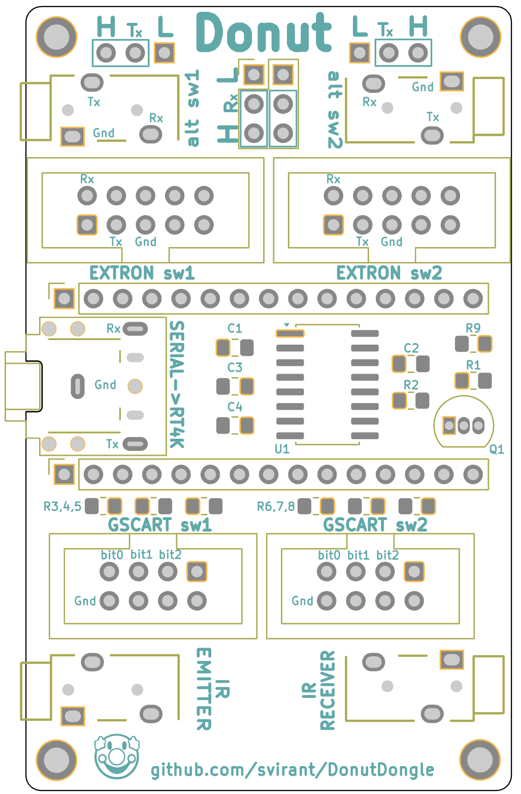
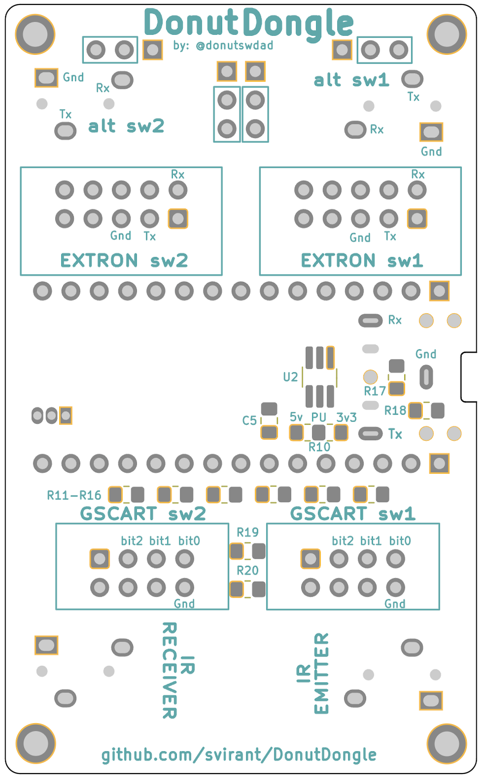
PCB
v1.0
Schematic
v1.0
Bill of Materials (BOM)
- 3D Printed Dount Dongle Case
- 3D Printed VGA Adapter Case [Courtesy of HerraAAV3 on the RetroTink Discord]
- Digikey shared list
- AliExpress wish list
- Donut Dongle PCB
| Qty | Designation | Part | Link | Notes |
|---|---|---|---|---|
| 2 | C1,C5 | 0.1 uf / 100nf 50V X7R 0805 Capacitor | Digikey | |
| 3 | C2-C4 | 0.33 uf / 330nf 50V X7R 0805 Capacitor | Digikey | |
| 1 | R1 | 30 OHM 1% 1/2W 0805 Resistor | Digikey | |
| 1 | R2 | 1K OHM 1% 1/8W 0805 Resistor | Digikey | |
| 10 | R3 - R10, R17, R19 | 10K OHM 1% 1/8W 0805 Resistor | Digikey | |
| 8 | R11 - R16, R18, R20 | 20K OHM 1% 1/8W 0805 Resistor | Digikey | |
| 1 | Q1 | 2N3904 NPN Transistor | AliExpress | |
| 1 | U1 | MAX3232 SOP-16 RS-232 Interface IC | AliExpress | |
| 1 | U2 | IC BUF NON-INVERT 5.5V SOT23-6 | Digikey or alternate | |
| 1 | PH1 | PJ-307 3.5mm Stereo Jack | AliExpress | |
| or 1x 3.5mm Audio Jack Socket | AliExpress | Like the PJ-307 but missing the inner 2 poles which arent needed anyways | ||
| 4 | J4,J9-11 | PJ-320 3.5MM Headphone Jack Audio Video Female | AliExpress | Color: PJ-320B DIP |
| 2 | J3,J6 | 2x5 Pin Double Row 2.54mm Pitch Straight Box Header | AliExpress | (Color: STRAIGHT TYPE, Pins: 10PCS DC3-10Pin) |
| 2 | J5,J8 | 2x4 Pin Double Row 2.54mm Pitch Straight Box Header | AliExpress | (Color: STRAIGHT TYPE, Pins: 10PCS DC3-8Pin) |
| 1 | (optional) | 3.5mm CHF03 1.5 Meters IR Infrared Remote Emission Cable | AliExpress | required for OSSC, RT5X (must be firmware version 3.7+) |
| 1 | (optional) | 3.5mm Infrared Remote Control Receiver Extension Cable | AliExpress | required for New IR Remote Control functionality |
| 2 | H1,H2 | 2.54mm Pitch Single Row Female 15P Header Strip | AliExpress | |
| 1 | Any 3.5mm / aux / stereo / trs / cable | AliExpress | ||
| 1 | usb-c cable for Arduino power & initial programming | AliExpress | ||
| 1 | Arduino Nano type c | Support RetroRGB! | Make sure the headers and esp the 2x3 pins are not soldered. | |
| 1 | JP2 | 2x3 Pin Double Row 2.54mm Pitch Header | Use the one that comes with the Arduino Nano. Jumper "H" for all switches unless instructed otherwise. | |
| 2 | JP3,4 | 1x3 Pin Single Row 2.54 Pitch Header | Dont buy two 1x3. Find any single row header and break off two 1x3 sections. Jumper "H" for all switches unless instructed otherwise. | |
| 4 | 2.54mm Jumper | AliExpress | You can also just solder blob "H". "L" jumper setting has only 1 use case atm. |
- Switch connection Cables
| Qty | Switch Type | Part | Link | Notes |
|---|---|---|---|---|
| 1 or 2 | TESmart HDMI | Any 3.5mm / aux / stereo / trs / Cable | AliExpress | strip 1 end to expose red(Rx)/white(Tx)/gnd wires for the green screw clamp OR use the TESmart_connector shown below |
| 1 or 2 | GscartSW/GCompSW | 2x4 Pin Double Row 2.54 Pitch Angled Box Header | AliExpress | (Color: RIGHT ANGLE TYPE, Pins: 10PCS DC3 8Pin), Solders onto EXT port. Or use the gscart_ext_connector shown below. |
| 1 or 2 | GscartSW/GCompSW | 2x4 Pin Female Header Ribbon Cable | AliExpress | (Pins: 2x4Pin, Color: Any length) |
| 1 | Extron | 2 Port DB9 to 2x5 Pin Female Header Ribbon Cable | AliExpress | |
| or 2x DB9 Male to 3.5mm Male Serial RS232 Cable 6feet | Amazon | "MUST" be wired as so: DB9 Male Pin 5 -> Sleeve, DB9 Male Pin 2 -> Tip, DB9 Male Pin 3 -> Ring | ||
| or make your own connectors in the "Connection Accessories" section below. |
At least 1 of the following VGA adapters is required:
- YC2VGA w/ Serial Tap v2: (enhanced s-video and composite as a bonus)
| Qty | Part | Link | Notes |
|---|---|---|---|
| 1 | Yellow RCA Composite jack | AliExpress | (Color: Yellow) |
| 1 | S-Video jack | AliExpress | (Color: A 4Pin) |
| 1 | PJ-320 3.5MM Headphone Jack Audio Video Female | AliExpress | (Color: 10PCS PJ-320) |
| 1 | VGA Male Connector [L717HDE15PD4CH4R-ND] | Digikey |
- VGA Passthrough w/ Shared Serial Tap:
- Confirmed compatible with the Scalable Video Switch and it's auto profiles.
| Qty | Part | Link | Notes |
|---|---|---|---|
| 1 | VGA Male Connector [L717HDE15PD4CH4R-ND] | Digikey | |
| 1 | VGA Female Connector | AliExpress | (Color: DB15 3.08) |
| 1 | PJ-320 3.5MM Headphone Jack Audio Video Female | AliExpress | (Color: 10PCS PJ-320) |
| 2 | #4-40 x 3/4" screw (optional) | Ebay |
Connection Accessories (optional)
- gscart/gcomp EXT connector
| Qty | Part | Link | Notes |
|---|---|---|---|
| 1 | 2x4 Pin Double Row 2.54 Pitch Angled Box Header | AliExpress | (Color: RIGHT ANGLE TYPE, Pins: 10PCS DC3 8Pin) |
| 6 | Pogo-Pin | Digikey |
- TESmart connector
| Qty | Part | Link | Notes |
|---|---|---|---|
| 1 | PJ-320 3.5MM Headphone Jack Audio Video Female | AliExpress | (Color: 10PCS PJ-320) |
- MT-VIKI / Extron / DB9 connector
| Qty | Part | Link | Notes |
|---|---|---|---|
| 1 | PJ-320 3.5MM Headphone Jack Audio Video Female | AliExpress | (Color: 10PCS PJ-320) |
| 1 | DB9 Male connector | AliExpress | (Color: Male head) |
| 2 | #4-40 1/4" pan head screw | Amazon |
Programming an Arduino Nano
I recommend the Official Arduino IDE and guide if you're unfamiliar with Arduinos. All .ino files used for programming are listed above. The following Libraries will also need to be added in order to Compile successfully.
- Libraries:
- <IRremote.hpp> "IRremote" available through the built-in Library Manager under "Tools" -> "Manage Libraries..."
- <AltSoftSerial.h> Follow these steps to add AltSoftSerial.h
- Goto https://github.com/PaulStoffregen/AltSoftSerial
- Click the GREEN "<> Code" box and "Download ZIP"
- In Arduino IDE; goto "Sketch" -> "Include Library" -> "Add .ZIP Library"
Steps to program the Donut Dongle
- 1 - Click the green "<> Code" button above and "Download ZIP".
- 2 - Extract the .zip file and open up the "Donut_Dongle.ino" file in the Arduino IDE. It will ask if you would like to move this file inside a folder, select OK.
- 3 - With the source code now open, select "Tools" -> "Board" -> "Arduino AVR Boards" -> "Arduino Nano"
- 4 - Connect the Donut Dongle device to your PC or Mac using the usb-c cable. You should see an LED light up when connected.
- 5 - With the Donut Dongle now connected, select it's "port" by going to "Tools" -> "Port", and select the port that starts with "/dev/cu.usbserial-" (on Mac) or "COM" if on PC.
- 6 - From the menu at the top, select "Sketch" -> "Verify/Compile". If everything is setup properly, you should see a message in the bottom corner saying "Done compiling".
- 7 - Now select "Sketch" -> "Upload". You should see the LEDs on the Donut Dongle flicker and a message that says "Done uploading." if successful.
- If you get errors, see the section below about changing the "Bootloader" type.
- 8 - Disconnect the usb-c cable from your computer and give it a whirl! You can repeat these steps in the future to make any other changes or update if a newer firmware is ever released.
- 9 - It's also best practice when unplugging/reconnecting cables to the Donut Dongle, that you do so with the power disconnected.
How to Use
-
Make sure "Auto Load SVS" is "On" under the RT4K Profiles menu.
-
The RT4K checks the /profile/SVS subfolder for profiles and need to be named: S<input number>_<user defined>.rt4 For example, SVS input 2 would look for a profile that is named S2_SNES.rt4. If there’s more than one profile that fits the pattern, the first match is used.
-
Check the RT4K Diagnostic Console for Serial commands being received as confirmation.
Troubleshooting
-
When (un)plugging aux cables from "alt sw1" or "alt sw2" ports make sure Donut Dongle power is disconnected. Sometimes the onboard MAX3232 chip can lock up if this is not done.
- To fix lockup, power off switch and DD (Donut Dongle). Disconnect/reconnect aux cable from DD and power up switch first, then DD last.
-
Some Arduino Nanos come with an Old Bootloader and won't Upload unless specified. If you get errors when trying to upload, swap to this option as a possible fix.
SVS Profile numbering scheme
| SVS = 1 (default) | Profile # | Notes |
|---|---|---|
| Extron sw1 / alt sw1 | 1 - 99 | also for TESmart, MT-ViKi, Otaku Games Scart 10 devices |
| Extron sw2 / alt sw2 | 101 - 199 | also for TESmart, MT-ViKi, Otaku Games Scart 10 devices |
| GSCART sw1 | 201 - 208 | |
| GSCART sw2 | 209 - 216 |
Remote Button Profiles are not used when SVS=1
| SVS = 0 | Profile # | Notes |
|---|---|---|
| Extron sw1 / alt sw1 | 13 - 99 | also for TESmart, MT-ViKi, Otaku Games Scart 10 devices |
| Extron sw2 / alt sw2 | 101 - 199 | also for TESmart, MT-ViKi, Otaku Games Scart 10 devices |
| GSCART sw1 | 201 - 208 | |
| GSCART sw2 | 209 - 216 |
Remote Button Profiles 1-12 are used for Extron sw1 when SVS=0
| SVS = 2 | Profile # | Notes |
|---|---|---|
| Extron sw1 / alt sw1 | 1 - 99 | also for TESmart, MT-ViKi, Otaku Games Scart 10 devices |
| Extron sw2 / alt sw2 | 101 - 199 | also for TESmart, MT-ViKi, Otaku Games Scart 10 devices |
| GSCART sw1 | N/A | |
| GSCART sw2 | 213 - 216 | inputs 5-8 |
Remote Button Profiles 1-12 are used for GSCART sw1 inputs 1-8 and GSCART sw2 inputs 1-4 when SVS=2
The following is from the .ino file itself. Refer to it directly for all Advanced Options.
/*
////////////////////
// OPTIONS //
//////////////////
*/
uint8_t const debugE1CAP = 0; // line ~495
uint8_t const debugE2CAP = 0; // line ~768
uint8_t const debugState = 0; // line ~432
uint16_t const offset = 0; // Only needed for multiple Donut Dongles (DD). Set offset so 2nd,3rd,etc boards don't overlap SVS profiles. (e.g. offset = 300;)
// MUST use SVS=1 on additional DDs. If using the IR receiver, recommended to have it only connected to the DD with lowest offset.
uint8_t const SVS = 1; // "Remote" profiles are profiles that are assigned to buttons 1-12 on the RT4K remote. "SVS" profiles reside under the "/profile/SVS/" directory
// on the SD card. This option allows you to choose which ones to call when a console is powered on. Remote profiles allow you to easily change
// the profile being used for a console's switch input if your setup is in flux. SVS require you to rename the file itself on the SD card which is
// a little more work. Regardless, SVS profiles will need to be used for console switch inputs over 12.
//
// **** Make sure "Auto Load SVS" is "On" under the RT4K Profiles menu. A requirement for most options ****
//
// 0 - use "Remote" profiles 1-12 for up to 12 inputs on 1st Extron Switch and SVS 13 - 99 for everything over 12. Only SVS profiles are used on 2nd Extron Switch if connected.
//
// - remote profiles 1-12 for 1st Extron or TESmart Switch (If S0 below is set to true - remote profile 12 is used when all ports are in-active)
// - SVS 12 - 99 for 1st Extron or TESmart (S0 is true)
// - SVS 13 - 99 for 1st Extron or TESmart (S0 is false)
// - SVS 101 - 199 for 2nd Extron or TESmart
// - SVS 201 - 208 for 1st gScart
// - SVS 209 - 216 for 2nd gScart
//
// 1 - use only "SVS" profiles.
// Make sure "Auto Load SVS" is "On" under the RT4K Profiles menu
// RT4K checks the /profile/SVS subfolder for profiles and need to be named: "S<input number>_<user defined>.rt4"
// For example, SVS input 2 would look for a profile that is named S2_SNES.rt4
// If there’s more than one profile that fits the pattern, the first match is used
//
// - SVS 1 - 99 for 1st Extron or TESmart
// - SVS 101 - 199 for 2nd Extron or TESmart
// - SVS 201 - 208 for 1st gScart
// - SVS 209 - 216 for 2nd gScart
// - SVS 0 for S0 option mentioned below
//
// ** If S0 below is set to true, create "/profile/SVS/S0_<user defined>.rt4" for when all ports are in-active. Ex: S0_HDMI.rt4
//
// 2 - use "Remote" profiles 1-12 for gscart/gcomp switches. Remote profile 1-8 for 1st gscart switch, 9-12 for inputs 1-4 on 2nd gscart switch.
// inputs 5-8 on the 2nd gscart switch will use SVS profiles 213 - 216
//
// - remote profiles 1-8 for 1st gScart, 9 - 12 for first 4 inputs on 2nd gScart (If S0 below is set to true - remote profile 12 is used when all ports are in-active)
// - SVS 213 - 216 for remaining inputs 5 - 8 on 2nd gScart
// - SVS 1 - 99 for 1st Extron or TESmart
// - SVS 101 - 199 for 2nd Extron or TESmart
//
bool const S0 = false; // (Profile 0) default is false
//
// ** Recommended to remove any /profile/SVS/S0_<user defined>.rt4 profiles and leave this option set false if using in tandem with the Scalable Video Switch. **
// ** Does not work with TESmart HDMI switches **
//
// For SVS=0; set true to load "Remote Profile 12" when all ports are in-active on SW1 (and SW2 if connected).
// You can assign it to a generic HDMI profile for example.
// If your device has a 12th input, SVS will be used instead. "If" you also have an active 2nd Extron Switch, Remote Profile 12
// will only load if "BOTH" switches have all in-active ports.
//
// For SVS=1, /profile/SVS/ "S0_<user defined>.rt4" will load instead of Remote Profile 12
//
// For SVS=2, Remote Profile 12 will be used instead of "S0_<user defined>.rt4"
//
//////////////////////////
// Choosing the above two options can get quite confusing (even for myself) so maybe this will help a little more:
//
// when S0=0 and SVS=0, button profiles 1 - 12 are used for EXTRON sw1, and SVS for EVERYTHING else
// when S0=0 and SVS=1, SVS profiles are used for everything
// when S0=0 and SVS=2, button profiles 1 - 8 are used for GSCART sw1, 9 - 12 for GSCART sw2 (ports 1 - 4), and SVS for EVERYTHING else
// when S0=1 and SVS=0, button profiles 1 - 11 are used for EXTRON sw1 and Remote Profile 12 as "Profile S0", and SVS for everything else
// when S0=1 and SVS=1, SVS profiles for everything, and uses S0_<user defined>.rt4 as "Profile 0"
// when S0=1 and SVS=2, button profiles 1 - 8 are used for GSCART sw1, 9 - 11 for GSCART sw2 (ports 1 - 3) and Remote Profile 12 as "Profile S0", and SVS for EVERYTHING else
//
//////////////////////////
// For Extron Matrix switches that support DSVP. RGBS and HDMI/DVI video types.
#define automatrixSW1 false // set true for auto matrix switching on "SW1" port
#define automatrixSW2 false // set true for auto matrix switching on "SW2" port
///////////////////////////////
uint8_t const ExtronVideoOutputPortSW1 = 1; // For certain Extron Matrix models, must specify the video output port that connects to RT4K
uint8_t const ExtronVideoOutputPortSW2 = 1; // can also be used for auto matrix mode as shown in next option
///////////////////////////////
uint8_t const vinMatrix[65] = {0, // MATRIX switchers // When auto matrix mode is enabled: (automatrixSW1 / SW2 defined above)
// set to 0 for the auto switched input to tie to all outputs
// set to 1 for the auto switched input to trigger a Preset
// set to 2 for the auto switched input to tie to "ExtronVideoOutputPortSW1" / "ExtronVideoOutputPortSW2"
//
// For option 1, set the following inputs to the desired Preset #
// (by default each input # is set to the same corresponding Preset #)
1, // input 1 SW1
2, // input 2
3, // input 3
4, // input 4
5, // input 5
6, // input 6
7, // input 7
8, // input 8
9, // input 9
10, // input 10
11, // input 11
12, // input 12
13, // input 13
14, // input 14
15, // input 15
16, // input 16
17, // input 17
18, // input 18
19, // input 19
20, // input 20
21, // input 21
22, // input 22
23, // input 23
24, // input 24
25, // input 25
26, // input 26
27, // input 27
28, // input 28
29, // input 29
30, // input 30
30, // input 31
30, // input 32
//
// ONLY USE FOR 2ND MATRIX SWITCH on SW2
1, // 2ND MATRIX SWITCH input 1 SW2
2, // 2ND MATRIX SWITCH input 2
3, // 2ND MATRIX SWITCH input 3
4, // 2ND MATRIX SWITCH input 4
5, // 2ND MATRIX SWITCH input 5
6, // 2ND MATRIX SWITCH input 6
7, // 2ND MATRIX SWITCH input 7
8, // 2ND MATRIX SWITCH input 8
9, // 2ND MATRIX SWITCH input 9
10, // 2ND MATRIX SWITCH input 10
11, // 2ND MATRIX SWITCH input 11
12, // 2ND MATRIX SWITCH input 12
13, // 2ND MATRIX SWITCH input 13
14, // 2ND MATRIX SWITCH input 14
15, // 2ND MATRIX SWITCH input 15
16, // 2ND MATRIX SWITCH input 16
17, // 2ND MATRIX SWITCH input 17
18, // 2ND MATRIX SWITCH input 18
19, // 2ND MATRIX SWITCH input 19
20, // 2ND MATRIX SWITCH input 20
21, // 2ND MATRIX SWITCH input 21
22, // 2ND MATRIX SWITCH input 22
23, // 2ND MATRIX SWITCH input 23
24, // 2ND MATRIX SWITCH input 24
25, // 2ND MATRIX SWITCH input 25
26, // 2ND MATRIX SWITCH input 26
27, // 2ND MATRIX SWITCH input 27
28, // 2ND MATRIX SWITCH input 28
29, // 2ND MATRIX SWITCH input 29
30, // 2ND MATRIX SWITCH input 30
30, // 2ND MATRIX SWITCH input 31
30, // 2ND MATRIX SWITCH input 32
};
// ** Must be on firmware version 3.7 or higher **
uint8_t const RT5Xir = 0; // 0 = disables IR Emitter for RetroTink 5x
// 1 = enabled for Extron sw1 / alt sw1, TESmart HDMI, MT-ViKi, or Otaku Games Scart Switch if connected
// sends Profile 1 - 10 commands to RetroTink 5x. Must have IR LED emitter connected.
//
// 2 = enabled for gscart switch only (remote profiles 1-8 for first gscart, 9-10 for first 2 inputs on second gscart)
//
// 3 = enabled for Extron sw2 / alt sw2, TESmart HDMI, MT-ViKi, or Otaku Games Scart Switch if connected
// sends Profile 1 - 10 commands to RetroTink 5x. Must have IR LED emitter connected.
uint8_t const OSSCir = 0; // 0 = disables IR Emitter for OSSC
// 1 = enabled for Extron sw1 switch, TESmart HDMI, or Otaku Games Scart Switch if connected
// sends Profile 1 - 14 commands to OSSC. Must have IR LED emitter connected.
//
// 2 = enabled for gscart switch only (remote profiles 1-8 for first gscart, 9-14 for first 6 inputs on second gscart)
uint8_t const MTVir = 0; // Must have IR "Receiver" connected to the Donut Dongle for option 1 & 2.
// 0 = disables IR Receiver -> Serial Control for MT-VIKI 8 Port HDMI switch
//
// 1 = MT-VIKI 8 Port HDMI switch connected to "Extron sw1"
// Using the RT4K Remote w/ the IR Receiver, AUX8 + profile button changes the MT-VIKI Input over Serial.
// Sends auxprof SVS profiles listed below.
//
// 2 = MT-VIKI 8 Port HDMI switch connected to "Extron sw2"
// Using the RT4K Remote w/ the IR Receiver, AUX8 + profile button changes the MT-VIKI Input over Serial.
// Sends auxprof SVS profiles listed below. You can change them below to 101 - 108 to prevent SVS profile conflicts if needed.
// 3 = MT-VIKI 8 Port HDMI switch connected to BOTH "alt sw1" and "alt sw2"
// Use AUX7 and AUX8 buttons as described above.
//
uint8_t const TESmartir = 0; // Must have IR "Receiver" connected to the Donut Dongle for option 1 and above.
// 0 = disables IR Receiver -> Serial Control for TESmart 16x1 Port HDMI switch
//
// 1 = TESmart 16x1 HDMI switch connected to "alt sw1"
// Using the RT4K Remote w/ the IR Receiver, AUX7 + profile button changes the Input over Serial. AUX7 + AUX1 - AUX4 for Input 13 - 16.
// Sends SVS profile 1 - 16 as well.
//
// 2 = TESmart 16x1 HDMI switch connected to "alt sw2"
// Using the RT4K Remote w/ the IR Receiver, AUX8 + profile button changes the Input over Serial. AUX8 + AUX1 - AUX4 for Input 13 - 16.
// Sends SVS profile 101 - 116 as well.
//
// 3 = TESmart 16x1 HDMI switch connected to BOTH "alt sw1" and "alt sw2"
// Use AUX7 and AUX8 buttons as described above.
//
uint8_t const auxprof[12] = // Assign SVS profiles to IR remote profile buttons.
// Replace 1, 2, 3, etc below with "ANY" SVS profile number.
// Press SAFE button then profile button to load. Must have IR Receiver connected and Serial connection to RT4K.
//
//
{1, // SAFE + profile 1 button
2, // SAFE + profile 2 button
3, // SAFE + profile 3 button
4, // SAFE + profile 4 button
5, // SAFE + profile 5 button
6, // SAFE + profile 6 button
7, // SAFE + profile 7 button
8, // SAFE + profile 8 button
9, // SAFE + profile 9 button
10, // SAFE + profile 10 button
11, // SAFE + profile 11 button
12, // SAFE + profile 12 button
};
uint8_t const gctl = 0; // 1 = Enables gscart/gcomp manual input selection
// 0 = Disable (Default)
//
// ** Only supported on vers 5.x gscart/gcomp switches **
//
// AUX5 button + 1-8 button for gscart sw1, button 1 = input 1, etc
// AUX5 + 9-12 button to return to auto switching
//
// AUX6 button + 1-8 button for gscart sw2, button 1 = input 1, etc
// AUX6 + 9-12 button to return to auto switching
//
// (RT5x and OSSC may require a repeat of the button combo for the IR signal to send.)
char const auxpower[] = "LG"; // AUX8 + Power button sends power off/on via IR Emitter. "LG" OLEX CX is the only one implemented atm.
No comments yet. Be the first to ask about this board.