pico_test_synth
PublicLoading 3D model… large boards can take a moment.
pico_test_synth
A simple
Raspberry Pi Pico RP2040 or Pico 2 RP2350-based
synth to experiment with synthio and Mozzi.

pico_test_synth2
pico_test_synth, the original
video demo
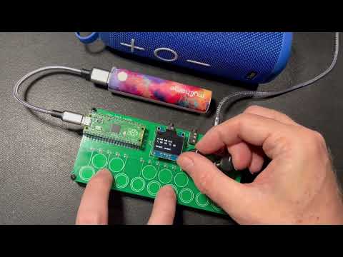
** Available on Tindie **
Features
- PCM5102 I2S DAC footprint for high-quality stereo audio out
- Optoisolated MIDI Input via MIDI TRS-A 3.5mm jack
- MIDI output via MIDI TRS-A 3.5mm jack
- Two pots for controlling parameters
- One switch for controlling parameters
- 16 capsense touch buttons for synth triggering
- USB MIDI in/out of course too
- (NOTE: the pico_test_synth1 PCB will NOT work with the Pico2, since its RP2350 chip has a hardware error)
pico_test_synth2 vs pico_test_synth
- Both use the same components
- Both run the same code
- Both fit in the same enclosure
pico_test_synth2drawn in Kicad;pico_test_synthdrawn in Eaglepico_test_synth2has square buttons;pico_test_synthhas round buttonspico_test_synth2can work with Pico 2 and Picopico_test_synthcan only work with Pico1
Software
Programs written for qtpy_synth
will work with this board too with minimal changes.
Some programs written specifically for this board:
- TBish - a TB303-like synth demo (video demo)
- monosynth1 - a full Moog-like monosynth written in Arduino & Mozzi
- hwtest - test out the hardware with a simple synth (video demo)
- wavesynth - port of wavesynth for qtpy_synth board with some improvements
See also:
- CircuitPython Synthio Tricks
- Contains many other synthio examples that can work with this synth with minimal changes
- Synthio Tutorial
- a getting-started guide for
synthioending with some full synthesiser voices
- a getting-started guide for
Enclosure
As seen in the photos, there is a simple 3d-printable enclosure available on Printables. It's fast to print and you can snap the PCB in to quickly get started, or use M2.5 screws and nuts to secure the PCB more permanently.
Pins used
The board uses all of the Raspberry Pi Pico pins:
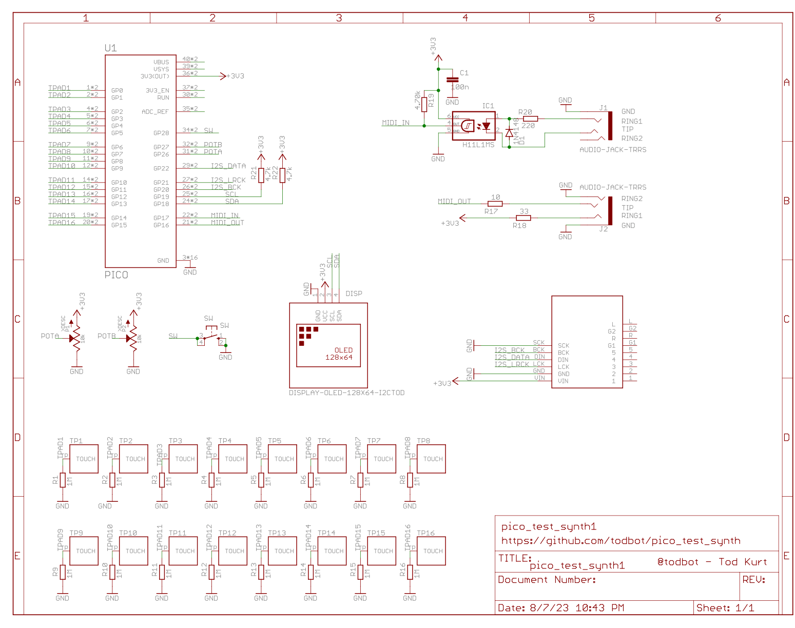
board.GP28- middle buttonboard.GP27- right knobboard.GP26- left knobboard.GP22- I2S databoard.GP21- I2S LR clockboard.GP20- I2S bit clockboard.GP19- I2C SCL for OLED displayboard.GP18- I2C SDA for OLED displayboard.GP17- TRS UART MIDI inboard.GP16- TRS UART MIDI outboard.GP15..board.GP0-- touch pads 1-16
For more details see hwtest/code.py.
Schematics
pico_test_synth2

pico_test_synth, original
Ask about this board
No comments yet. Be the first to ask about this board.